Home
Home

 Artists
 Search
 Recent
 Random
 Posts
Posts
 DMs
DMs
 Tags
Tags
 Random
 Importer
 Import
 FAQ
FAQ
 Account
 Register
 Favorites
 Login
Login

EXCLUSIVE - RGB PKE Meter Electronics Guide and Notes (Patreon)
Downloads
Content
Here are some notes for an Arduino project that gives you some lights on the 3D Printed RGB PKE Meter. The 3D printed body is sized to house two separate electronic modules:
- The PKE main screen - Controlled by a combination of an Arduino UNO and a 2.8" TFT screen
- The PKE antenna lights - Controlled by an Arduino Nano and blinking LED setup and push buttons controlling blink rates
On this post, I have attached the Arduino code I composed to control the light and TFT screen effects.
Here are the parts that you'll need for my install. (I found Amazon listings that are close to my parts, although I suggest shopping around as some of these listings have more than what you need to complete the project)
- Breadboard
- Arduino Uno
- Arduino Nano
- 2.8" TFT Screen
- Jumper wires
- LEDs (2x White or Yellow)
- Resistors
- Switch
- DC male plug for power
- Push buttons
- 9V Battery (x2)
PKE Screen Display
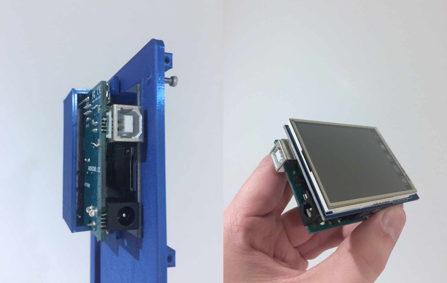
The 3D Printed PKE meter is designed to house a 2.8" TFT screen display that is connected to a standard Arduino Uno. These two components are designed to to plug together - no fancy wiring required.

The Ardunio+TFT combo is mounted to the front face of the PKE meter using the mounting bracket.

When fully assembled, the 3D printed PKE chassis allows easy access to the Ardunio's USB port and the power port. While this is not accurate to the cartoon, it is certainly functional! This means you can re-program the Ardunio and screen without having to disassemble the part.

To power the screen, I used a DC male plug and wire that wraps around to the backside of the PKE. The cartoon version, has a wire like this depicted on the opposite side - but here it serves a functional purpose to supply power to the screen. The wire is hooked to a 9V battery on the inside of the main body.

After loading the Ardunio code and powering it up, the PKE radar effect will play on the main screen. The code is designed to randomly create different class 5 signals every time it is booted up! (Note: The Arduino code sketch requires the MCUFRIEND_kbv library to compile.)

Antenna Lights
The antenna lights follow a very simple wiring diagram with an Arduino Nano and some push buttons. (Note: This is a separate circuit from the TFT display)

When the Ardunio sketch code is compiled to the Nano, the push buttons will toggle different blink sequences. When the lights are first powered, the blink rate will be set to slow. One toggle will increase the rate to "medium" speed. The other toggle will set a "fast" blink rate.

When powered on, the LEDs will have an alternating blink effect with speed rates controlled by the front push buttons.

Files